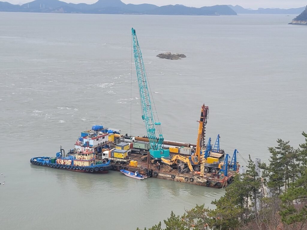
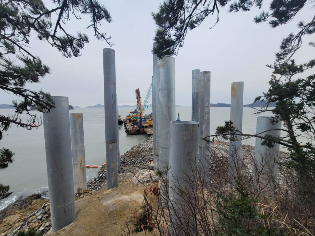
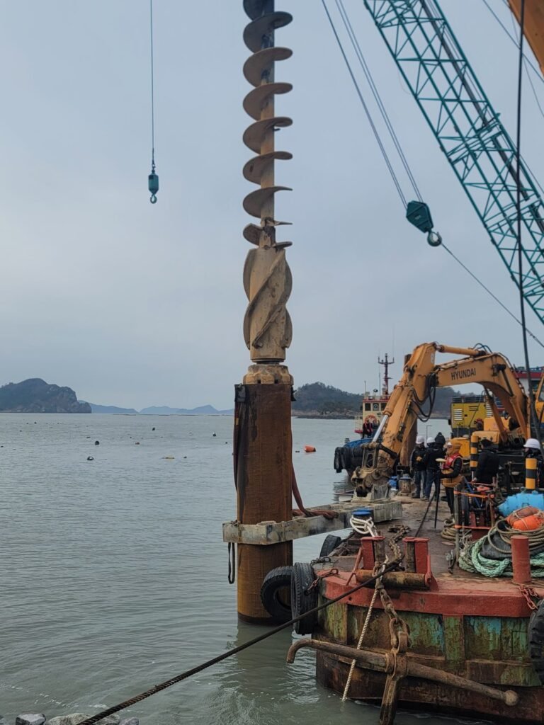
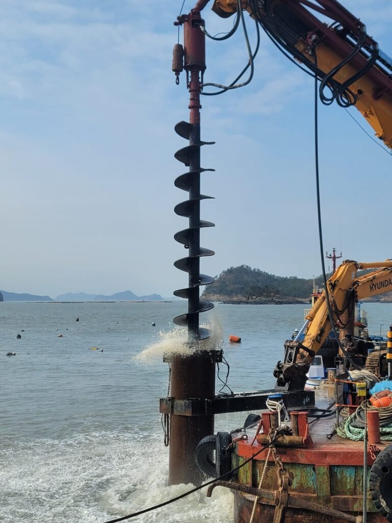
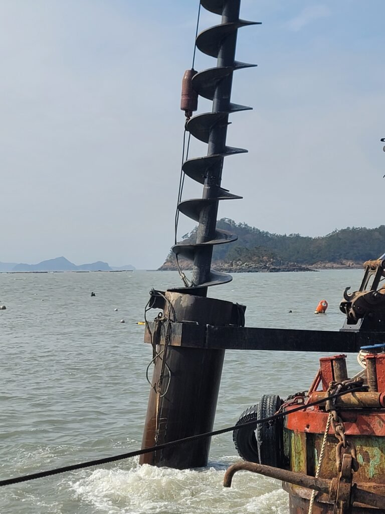
Offshore piling for the marine bridge and observation deck at Sebang Sunset Observatory, off Gahak-ri, Jisan-myeon, Jindo County, South Korea.
Two things make this job stand out. First, it was large-diameter offshore drilling in a fast-current archipelago channel, carried out in winter conditions. Second, the 15mm annular clearance had to be held while the working platform itself kept moving.
1. Drilling Specification — A 15mm Clearance on a Moving Platform
Item
Specification
Pile outside diameter
Ø1,000 mm (39.4 in), 34 mm (1.34 in) wall, high-strength steel pipe
Drill bit
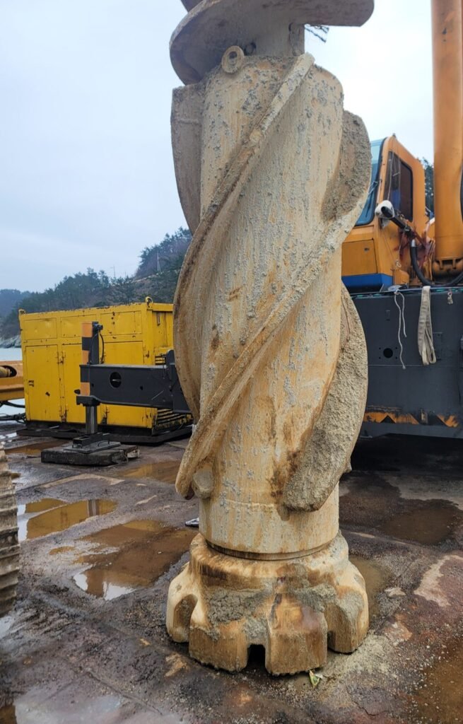
Ø1,030 mm (40.6 in) large-diameter button bit
Clearance per side
15 mm (0.59 in)
Pile count
20 piles total (13 onshore + 7 offshore)
Pile length
9.9 m – 28.8 m (32 – 94 ft), including pylon piles
Drilled depth
5.0 m (16.4 ft) per hole (onshore soft rock / offshore weathered soil)
Hammer set
Topdrill TG640C hammer + Ø1,030 mm bit
Clearance per side 15 mm = (1,030 mm hole − 1,000 mm pile OD) ÷ 2
A Ø1,000mm pipe pile has to enter a Ø1,030mm hole. The gap on each side is 15 mm — about the width of a finger joint.
Before going further, one honest qualification. A 15mm clearance is not, by itself, a remarkable number. On a stable onshore site with a fixed rig, holes at 30–50 m depth are routinely held to around 10 mm per side. There is no point dressing up the figure.
What made this job difficult is that the platform was not fixed. Holding the same 15 mm while the vessel moves with the sea is a different problem entirely from holding it on solid ground. The rig is not providing the reference — the reference itself keeps moving.
If a hole drilled 5 m below the waterline loses verticality by even a small margin, the pile binds partway down. From there the options are re-drilling, reaming, or pulling the pile and relocating it. Where barge charter and crane hire run by the hour, that carries a real cost.
The deciding factor here was never penetration rate. It was verticality.
2. Four Conditions Working Against the Job
Strong tidal current: The waters off Jindo are known for fast currents. Work was possible only within narrow slack-water windows.
Barge roll and pitch: Even light swell moved the entire barge. Precise weight control on the hammer was compromised, and even reliable penetration-rate timing became impossible.
Winter marine weather: Cold, wind and frequent marine advisories severely limited available working days.
Sloping seabed: The seabed was not level, creating a high risk that the bit would skate off-axis on first contact.
3. Air Supply — Effective Working Pressure Changes Underwater
Compressor configuration
SULLAIR 1100 CFM × 1
XRVS487 1050 CFM × 2
Total supply approx. 3,200 CFM / operating pressure approx. 16 – 17.5 bar (232 – 254 psi)
A resistance that does not exist onshore: seawater back pressure
A DTH hammer reciprocates its piston on the pressure differential between supply air and exhaust. Onshore the exhaust discharges freely to atmosphere. In submerged drilling the situation is entirely different, because the exhaust stream has to push against the hydrostatic head of the water column on its way out.
Effective working pressure = supply pressure − submerged exhaust back pressure
Every 10 m of water depth applies roughly 1 bar (0.1 MPa) of back pressure directly against the working chamber. Even with the surface gauge reading a steady 17 bar, the pressure the piston actually works on downhole is lower. Since this translates into reduced impact energy and lower ROP, it belongs in the calculation from the start.
On this project, sufficient air volume and pressure were available and it caused no difficulty. However, where site conditions do not allow multiple compressors, or where only lower-pressure units are available, back pressure must be factored in. An air package sized exactly to onshore requirements can fall short underwater.
4. The Sequence That Protected the 15mm
Step 1 — Set down with rotation stopped, load applied vertically
If the auger is turning when the bit contacts a sloping seabed, the bit skates and the axis bends toward the weaker, lower side. When that happens, torsional shear concentrates on the outer carbide gauge buttons, fracturing tips or initiating asymmetric wear.
On this project the bit was landed with rotation fully stopped, using only hammer dead weight and rig feed force to seat it vertically on the slope. The hammer was raised and lowered in a slow pumping motion, taking as long as needed until the bit was firmly bedded perpendicular to the slope. If the first 300 mm is off, nothing at 5 m will correct it.
Step 2 — Begin rotation only after alignment is confirmed
Only once the bit was confirmed to be cutting straight into the formation was slow clockwise torque applied, entering normal percussive rotary drilling.
Step 3 — Casing guide frame to restrain movement
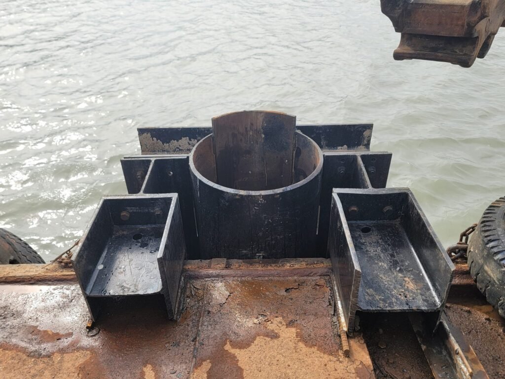
If the hammer loses centre on a barge moving with the swell, the result is bit binding or joint failure. To prevent this, a casing guide frame was welded to the forward edge of the barge deck, mechanically restraining the pile head on all sides.
Any loss of verticality wears the gauge buttons, and worn gauge means a hole narrower than Ø1,030 mm. Like a rifle barrel off by one degree missing the target by metres downrange, control in the first degree was the key to the whole operation.
Following this sequence, the hammer set handled two formations of completely different character — onshore soft rock and offshore weathered soil — on a single configuration, completing all 20 piles. When conditions allowed, offshore holes ran at roughly one hour each.
5. Pre-Job Checklist for Offshore Large-Diameter Work
Double the lubrication rate, without exception: Seawater and fine abrasive marine sand continuously entering the hammer wash away the sealing oil film (washout). To defend against this, deliver a high-viscosity rock drill oil with EP anti-wear additives, ISO VG 320 – 460 grade, at roughly twice the normal hourly requirement to guard against seizure.
Fresh-water wash and corrosion protection immediately after shutdown: A hammer left salt-laden after marine work will have seized threads within a day. Washing inside and out with clean fresh water as soon as it comes up, then applying corrosion-inhibiting grease before storage, avoids this.
Never apply torch heat or sledge hammer blows during breakout: Large DTH casings are precision heat-treated. Direct heat or impact produces micro-cracking and permanent scrap.
Monitor gauge wear: On pile-insertion drilling, gauge wear means hole-diameter loss, and hole-diameter loss means re-drilling.
Offshore Large-Diameter Drilling — Talk to Topdrill
Since 1999 Topdrill has designed and manufactured large-diameter DTH hammers and bits up to 40 inches in-house, supplying contractors in over 100 countries.
On a marine piling site, an hour of standby converts directly into barge charges and equipment cost. So Topdrill does not stop at supplying hardware.
Compressor volume and pressure matched to actual water depth, accounting for back pressure
Bit diameter and clearance review against pile outside diameter, including gauge wear margin
Lubrication specification for seawater exposure and seasonal temperature
Troubleshooting support for bit binding, hole deviation, no-percussion and related faults
All of the above engineering support is provided free of charge ahead of mobilisation. If you have offshore large-diameter piling coming up, it is worth talking to our R&D centre before the equipment goes on the barge.
Topdrill Technical Support & R&D Centre / topdrill.org
(※ Specifications and figures are based on the project design documents and site records. Results vary with formation conditions and equipment configuration.)

![[Photo ③] Site overview. Barge, crawler crane and tug working against the rock shoreline, with land-section piles already standing.](https://topdrill.org/wp-content/uploads/2026/08/20240201_112442-1024x768.jpg)